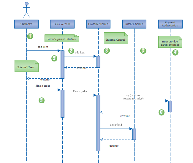

They are drawn from the sender to the receiver. Messages depict the invocation of operations are shown horizontally. Objects work together by communicating or interacting with one another. Objects take on the responsibility for things like managing data, moving data around in the system, responding to inquiries, and protecting the system. Messages between objects are represented by arrows that point from sender object to the receiver object.Įverything in an object-oriented system is accomplished by objects. Each object also has its timeline represented by a dashed line below the object. Often, an anonymous object (:Account) may be used to represent any object in the class.

Object names can be specific (e.g., myAccount) or they can be general (e.g., myAccount :Account). These indicate the existence of the object. A lifeline is represented by dashed vertical line drawn below each object.

LifelineĮntities of participants in a collaboration (scenario) are written horizontally across the top of the diagram. The three ways of naming an object are shown in Figure below. An object can be named in one of three ways: the object name, the object name and its class, or just the class name (anonymous object). In the UML, an object in a sequence diagram is drawn as a rectangle containing the name of the object, underlined. Fragments can also be added to represent control structures that operate on a group of messages.The Components of Sequence Diagram Object The order of objects and messages can be altered to make the diagram more readable and notes can be used to explain parts of the diagram. The choice will depend on what the modeler wants to represent. The elements that appear in Sequence diagrams can be either Classifiers such as Classes and Components or instances such as Objects and Component Instances. Sequence diagrams can also be created automatically from stack traces as a way of visualizing how a system functions. They are particularly useful when used to describe complex protocols or subsystem interactions that are difficult to understand unless presented graphically. They are more typically used by technical modelers to depict how messages are passed between application components and interfaces to achieve an outcome. The Sequence diagram can be used to model any set of messages that flow between two or more elements to produce a result. Ribbon: Design > Diagram > Add > UML Behavioral > Sequenceīrowser window Toolbar : New Diagram icon > UML Behavioral > Sequenceīrowser window context menu | Add Diagram.


 0 kommentar(er)
